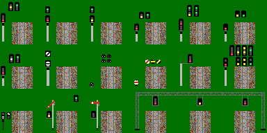
Top row, from left to right:
<ul>
<li>UK-style 3-aspect signal, on concrete mast, with signal idenfitication plate and sighting board (usually extend around three sides of the signal only. Signal is depicted as "on", with the "caution" and "off" aspects displayed above for reference.
<li>2-aspect signal, as previous. Signal depicted as "on", with "off" aspect displayed for reference.
<li>2-aspect colour-light repeater signal. Depicted "on", with "off" for reference.
<li>London Underground 2-aspect signals, with lower head height for sighting at a driver height of 2-2.5m as opposed to the more conventional 3-4m. Stop signal depicted as "on", also shown are "on" for a repeater signal, and the common "off".
<li>LU combined stop/repeater - arrangement on post separately is generally stop portion above the repeater portion. Signal shown as "stop" with "caution" and "off" for reference.
<li>New-style LED "searchlight" signal - all three colours are displayed through a single lens with LED arrays to show the expected aspect.
</ul>
Middle row:
<ul>
<li>(Not for simulation) LU Central Line ATO signals. White lamp in the middle is "manual stop" - only trains with working automatic controls may pass.
<li>Fiberoptic/LED "banner repeater". The unlit portion indicates the aspect of the next signal. Shown as "next signal on", with "next signal off" hown above. Direction of the diagonal may be wrong. The intention of these is to be "signals without signals". A repeater signal is part of the signalling sequence for the purposes of braking distances, etc., whereas the banner repeaters are not. They are often used at stations where platform furniture might obscure the driver's view of the starting signal.
<li>Position-light shunting signals, shown as "off". Traditional filament signals use a white bulb in the pivot point (so showing red-white in the "on" position), whereas new LED signals will show either red or white at the pivot as appropriate. Yellow signals are used at the exit from sidings to indicate that only one route is controlled (i.e. to the running lines), and that the signal might otherwise be passed if the points are set correctly (i.e. to a loco siding or head-shunt) - the equivalent procedure in BAHN would be to set an auxiliary route code for shunting movements, and use "not valid for these routes" in the signal settings. The original reason for this was not to have drivers knowingly passing red signals at danger.
<li>Disc equivalents of the previous. Yellow band on black indicates that head-shunting etc. is permitted (as previous).
<li>(Not necessarily for simulation) An example of a signal on a side gantry.
<li>(Not for simulation - shown for comparison) 4-aspect signals - traditional and LED varieties. The second array shows yellow only and is placed for enough above the base array to achieve the spacing that you would see at conventional lights.
</ul>
Bottom row:
<ul>
<li>Miniature banner repeater, shown as "next signal on" - "next signal off" shown alongside. These are typically used at canopied stations with curved platforms - a 10-car train might be able to see the starting signal while a 2-car train might not.
<li>(two-images, illustrative purpose only) LBSCR/SR-style semaphores with colour-light repeaters. These were used (IIRC) at fringes between colour-light signalling and semaphore signalling - typically as the last stop signal before entering the CL area.
<li>(three images) A possibility for an overhead gantry design (albeit with poor choice of colour for the structure). Careful observers will note that the central section can be reversed and repeated should more than three signals be needed. Shown are (L-R) a 3-aspect signal at danger, a 3-aspect LED signal at caution, and a 2-aspect signal at danger.
</ul>
Is there any interest in seeing some of the above?
The image in higher resolution

